
|
BraceWrap® Invention All Buckling Restrained Braces (BRBs) being constructed to date require a tube or shell that will encase the brace. However, because these tubes must be pre-manufactured, they can only be used in the construction of a new BRB. In other words, because the ends of an existing brace are connected to the building frame, one cannot slip a tube over the steel brace. This is a major limitation that prevents the above techniques to be used in retrofit of exiting conventional steel braces. In other words, once a steel brace has been erected (as in millions of existing buildings), the above techniques cannot be implemented to convert the ordinary steel brace to a BRB! To overcome the above shortcomings, QuakeWrap, Inc. has developed a new economical method of construction of BRB, named BraceWrap® that is described here. The invention can be applied to new construction as well as retrofit of bracing elements in existing buildings that were not constructed as a BRB.A copy of the US Patent #9,719,255 entitled "Buckling Reinforcement for Structural Members" by Prof. Ehsani is linked here. BraceWrap® utilizes the PileMedic® SuperLaminate™ developed by PileMedic, LLC (www.PileMedic.com). These laminates are manufactured with specially designed equipment. A resin is applied to one or more layers of a composite fabric such as glass, carbon, basalt, Kevlar, etc. fabric and the entire assembly is put through the equipment where it is subjected to heat and pressure. The result is a very thin (0.01-0.03 inch) thick laminate. These laminates are very strong with tensile strength exceeding 150,000 psi. A major advantage of these laminates is that the laminate has enough rigidity to stand by itself on its edge. -Frame-using-BraceWrap.JPG)
The steps in creating a BRB are shown in the above sketch. The ordinary steel brace (a), is first coated with a debonding material that is shown in dark green color (b). Next, a long enough piece of the 4-ft wide PileMedic® is cut and coated with a special epoxy paste that is provided as shown in dark grey color (c). This laminate is wrapped two or more times around the steel brace to create a tube. Additional 4-ft wide bands of PileMedic® are similarly applied with an adequate overlap along the length of the brace to create a continuous tube that covers substantially the full length of the steel brace. In the final stage (d), the bottom end of the tube is plugged and the tube is filled with a filler material such as concrete or grout. All of these operations can be performed with minimal equipment and the lightweight materials and tools are ideal for retrofit of higher floors where access is often a major cost consideration. Preliminary Testing of BraceWrap®The newly introduced BraceWrap® system was recently tested at the Structural Engineering Laboratory of the University of Arizona under the direction of Professor Robert Fleischman. In this proof of concept study, only two specimens were tested, one without any retrofit as a control specimen, and another that was retrofitted to a buckling restrained brace (BRB) prior to testing. As shown in below, Fig. (a) shows the steel brace. In Fig (b) duct tape has been bonded to the surface of the steel brace to serve as the debonding material. The yellow plastic spacers are supplied to ensure proper placement of the BraceWrap® and to provide a uniform edge or stand-off distance between the FRP shell and the steel brace. In Fig. (c) a 4-ft wide sheet of PileMedic® glass FRP laminate, coated with epoxy paste is being wrapped around the steel brace. The laminate comes in contact with the plastic spacers that define the diameter and shape of the jacket or shell being formed. The laminate length is determined based on the number of plies that are required to form the shell; the minimum is two plies but more plies can be used by simply using a longer piece of laminate. All these plies are bonded together with the epoxy paste that is applied to the laminate prior to wrapping. In step (d), the bottom of the jacket is sealed and the jacket is being filled with a grout. Additional 4-ft wide lamiantes are similarly applied with sufficient overlap length to create a continuous jacket that covers the entire length of the brace, shown in Fig. (e). 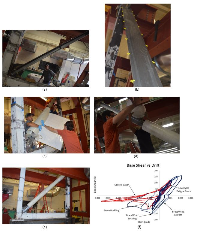
The test results are shown in Fig. (f). The red graph represents the control specimen that was not retrofitted. As expected, the specimen buckles in compression at an early load and the behavior exhibits little ductility or energy absorption. The blue graph represents the specimen that was retrofitted as a Buckling Restrained Brace (BRB) Frame. The hysteretic behavior of this specimen is much improved, showing larger energy dissipation. Unfortunately, this specimen failed prematurely before the full benefits of BraceWrap® could be realized. The 4-ft wide laminates were installed with only 4-inch overlap length. One of these overlap locations coincided with the mid-length of the brace and led to a premature failure of the jacket due to short overlap length. Another specimen is being constructed with larger overlap length to be tested in summer 2017. It is anticipated that the behavior of that specimen will be much closer to that of conventional Buckling Restrained Brace (BRB) frames. Publications:The following is a list of publications on this innovative solution for buckling restrained braced system:
|